Thursday, August 22, 2019

Introduction to Data Link Layer

Data Link Layer is second layer of OSI Layered Model. This layer is one of the most complicated layers and has complex functionalities and liabilities. Data link layer hides the details of underlying hardware and represents itself to upper layer as the medium to communicate.
Data link layer works between two hosts which are directly connected in some sense. This direct connection could be point to point or broadcast. Systems on broadcast network are said to be on same link. The work of data link layer tends to get more complex when it is dealing with multiple hosts on single collision domain.
Data link layer is responsible for converting data stream to signals bit by bit and to send that over the underlying hardware. At the receiving end, Data link layer picks up data from hardware which are in the form of electrical signals, assembles them in a recognizable frame format, and hands over to upper layer.
Data link layer has two sub-layers:
  • Logical Link Control: It deals with protocols, flow-control, and error control
  • Media Access Control: It deals with actual control of media

Functionality of Data-link Layer

Data link layer does many tasks on behalf of upper layer. These are:
  • Framing
    Data-link layer takes packets from Network Layer and encapsulates them into Frames.Then, it sends each frame bit-by-bit on the hardware. At receiver’ end, data link layer picks up signals from hardware and assembles them into frames.
  • Addressing
    Data-link layer provides layer-2 hardware addressing mechanism. Hardware address is assumed to be unique on the link. It is encoded into hardware at the time of manufacturing.
  • Synchronization
    When data frames are sent on the link, both machines must be synchronized in order to transfer to take place.
  • Error Control
    Sometimes signals may have encountered problem in transition and the bits are flipped.These errors are detected and attempted to recover actual data bits. It also provides error reporting mechanism to the sender.
  • Flow Control
    Stations on same link may have different speed or capacity. Data-link layer ensures flow control that enables both machine to exchange data on same speed.
  • Multi-Access
    When host on the shared link tries to transfer the data, it has a high probability of collision. Data-link layer provides mechanism such as CSMA/CD to equip capability of accessing a shared media among multiple Systems.

Transmission media

Transmission media is a pathway that carries the information from sender to receiver. We use different types of cables or waves to transmit data. Data is transmitted normally through electrical or electromagnetic signals.
An electrical signal is in the form of current. An electromagnetic signal is series of electromagnetic energy pulses at various frequencies. These signals can be transmitted through copper wires, optical fibers, atmosphere, water and vacuum Different Medias have different properties like bandwidth, delay, cost and ease of installation and maintenance. Transmission media is also called Communication channel.


Types of Transmission Media

Transmission media is broadly classified into two groups.
Wired or Guided Media or Bound Transmission MediaBound transmission media are the cables that are tangible or have physical existence and are limited by the physical geography. Popular bound transmission media in use are twisted pair cable, co-axial cable and fiber optical cable. Each of them has its own characteristics like transmission speed, effect of noise, physical appearance, cost etc.  
Wireless or Unguided Media or Unbound Transmission MediaUnbound transmission media are the ways of transmitting data without using any cables. These media are not bounded by physical geography. This type of transmission is called Wireless communication. Nowadays wireless communication is becoming popular. Wireless LANs are being installed in office and college campuses. This transmission uses Microwave, Radio wave, Infra red are some of popular unbound transmission media.


Spectrum Spreading

Spread Spectrum Signals

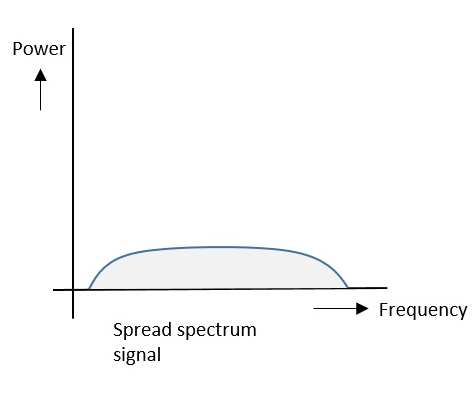
The spread spectrum signals have the signal strength distributed as shown in the following frequency spectrum figure.
Spread Spectrum Signals
Following are some of its features −
  • Band of signals occupy a wide range of frequencies.
  • Power density is very low.
  • Energy is wide spread.
With these features, the spread spectrum signals are highly resistant to interference or jamming. Since multiple users can share the same spread spectrum bandwidth without interfering with one another, these can be called as multiple access techniques.

FHSS and DSSS / CDMA

Spread spectrum multiple access techniques uses signals which have a transmission bandwidth of a magnitude greater than the minimum required RF bandwidth.
These are of two types.
  • Frequency Hopped Spread Spectrum (FHSS)
  • Direct Sequence Spread Spectrum (DSSS)

Frequency Hopped Spread Spectrum (FHSS)

This is frequency hopping technique, where the users are made to change the frequencies of usage, from one to another in a specified time interval, hence called as frequency hopping. For example, a frequency was allotted to sender 1 for a particular period of time. Now, after a while, sender 1 hops to the other frequency and sender 2 uses the first frequency, which was previously used by sender 1. This is called as frequency reuse.
The frequencies of the data are hopped from one to another in order to provide a secure transmission. The amount of time spent on each frequency hop is called as Dwell time.

Direct Sequence Spread Spectrum (DSSS)

Whenever a user wants to send data using this DSSS technique, each and every bit of the user data is multiplied by a secret code, called as chipping code. This chipping code is nothing but the spreading code which is multiplied with the original message and transmitted. The receiver uses the same code to retrieve the original message.

Comparison between FHSS and DSSS/CDMA

Both the spread spectrum techniques are popular for their characteristics. To have a clear understanding, let us take a look at their comparisons.
FHSSDSSS / CDMA
Multiple frequencies are usedSingle frequency is used
Hard to find the user’s frequency at any instant of timeUser frequency, once allotted is always the same
Frequency reuse is allowedFrequency reuse is not allowed
Sender need not waitSender has to wait if the spectrum is busy
Power strength of the signal is highPower strength of the signal is low
Stronger and penetrates through the obstaclesIt is weaker compared to FHSS
It is never affected by interferenceIt can be affected by interference
It is cheaperIt is expensive
This is the commonly used techniqueThis technique is not frequently used

Advantages of Spread Spectrum

Following are the advantages of spread spectrum −
  • Cross-talk elimination
  • Better output with data integrity
  • Reduced effect of multipath fading
  • Better security
  • Reduction in noise
  • Co-existence with other systems
  • Longer operative distances
  • Hard to detect
  • Not easy to demodulate/decode
  • Difficult to jam the signals
Although spread spectrum techniques were originally designed for military uses, they are now being used widely for commercial purpose.

Multiplexing

What is Multiplexing?

Multiplexing is a technique used to combine and send the multiple data streams over a single medium. The process of combining the data streams is known as multiplexing and hardware used for multiplexing is known as a multiplexer.
Multiplexing is achieved by using a device called Multiplexer (MUX) that combines n input lines to generate a single output line. Multiplexing follows many-to-one, i.e., n input lines and one output line.
Demultiplexing is achieved by using a device called Demultiplexer (DEMUX) available at the receiving end. DEMUX separates a signal into its component signals (one input and n outputs). Therefore, we can say that demultiplexing follows the one-to-many approach.

Why Multiplexing?

  • The transmission medium is used to send the signal from sender to receiver. The medium can only have one signal at a time.
  • If there are multiple signals to share one medium, then the medium must be divided in such a way that each signal is given some portion of the available bandwidth. For example: If there are 10 signals and bandwidth of medium is100 units, then the 10 unit is shared by each signal.
  • When multiple signals share the common medium, there is a possibility of collision. Multiplexing concept is used to avoid such collision.
  • Transmission services are very expensive.

History of Multiplexing

  • Multiplexing technique is widely used in telecommunications in which several telephone calls are carried through a single wire.
  • Multiplexing originated in telegraphy in the early 1870s and is now widely used in communication.
  • George Owen Squier developed the telephone carrier multiplexing in 1910.

Concept of Multiplexing

Multiplexing
  • The 'n' input lines are transmitted through a multiplexer and multiplexer combines the signals to form a composite signal.
  • The composite signal is passed through a Demultiplexer and demultiplexer separates a signal to component signals and transfers them to their respective destinations.

Advantages of Multiplexing:

  • More than one signal can be sent over a single medium.
  • The bandwidth of a medium can be utilized effectively.

Thursday, August 1, 2019

 Data :-Data can be analog or digital. Analog data are continuous and take continuous values. Digital data have discrete states and take discrete values.


 signal:- signal is an electrical or electromagnetic current that is used for carrying data from one device or network to another.

Signals can be analog or digital. Analog signals can have an infinite number of values in a range; digital signals can have only a limited number of values.


periodic signal:-signal is a periodic signal if it completes a pattern within a measurable time frame, called a period and repeats that pattern over identical subsequent periods. The completion of a full pattern is called a cycle. A period is defined as the amount of time (expressed in seconds) required to complete one full cycle.

Non-periodic Signal. Definition: A signal is considered to be non-periodic or a periodic signal when it does not repeat its pattern over a period (i.e. interval of time).


Analog Signal:-

An analog signal is a continuous wave denoted by a sine wave (pictured below) and may vary in signal strength (amplitude) or frequency (waves per unit time). The sine wave's amplitude value can be seen as the higher and lower points of the wave, while the frequency value is measured in the sine wave's physical length from left to right.
There are many examples of analog signals around us. The sound from a human voice is analog, because sound waves are continuous, as is our own vision, because we see various shapes and colors in a continuous manner due to light waves. Even a typical kitchen clock having its hands moving continuously can be represented as an analog signal.

Analog Signal - Sine Wave

Digital Signal

digital signal - a must for computer processing - is described as using binary (0s and 1s), and therefore, cannot take on any fractional values. As illustrated in the graphic below, digital signals retain a uniform structure, providing a constant and consistent signal. Because of the inherent reliability of the digital signal, technology using it is rapidly replacing a large percentage of analog applications and devices. 

For example, the wristwatch, showing the time of day, with its minute, hour, and sweeping second hands, is being replaced by the digital watch, which offers the time of day and other information using a numerical display. A typical digital signal is represented below. Note the equally dispersed 1s and 0s.

Digital signal with binary


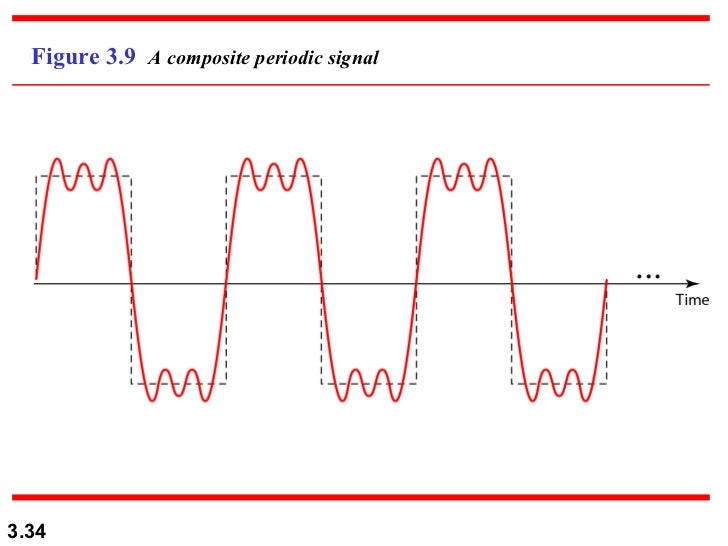
In data communications, we commonly use periodic analog signals and non periodic digital signals. Data Transmission Periodic analog signals can be classified as simple or composite. A simple periodic analog signal, a sine wave, cannot be decomposed into simpler signals. A composite periodic analog signal is composed of multiple sine waves.

note:- sine wave a curve representing periodic oscillations of constant amplitude as given by a sine function. 


note:- amplitude :-the angular distance of a celestial object from the true east or west point of the horizon at rising or setting.


Composite periodic Signal:-


A composite Signal Can be periodic or no periodic. 

A periodic   composite signal can be decomposed into a series of simple sine waves with discrete frequencies –
Frequencies that have integer values (1,2,3, and so on). 
A non-periodic composite signal can be   decomposed into a combination of an infinite number of simple sine waves with continuous frequencies, frequencies that have real values.Image result for a periodic composite signal


Data Communication | Transmission Impairment

In communication system, analog signals travel through transmission media, which tends to deteriorate the quality of analog signal. This imperfection causes signal impairment. This means that received signal is not same as the signal that was send.
Causes of impairment –

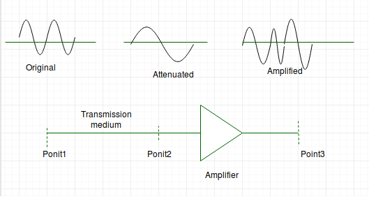
Attenuation – It means loss of energy. The strength of signal decreases with increasing distance which causes loss of energy in overcoming resistance of medium. This is also known as attenuated signal. Amplifiers are used to amplify the attenuated signal which gives the original signal back.


Attenuation is measured in decibels(dB). It measures the relative strengths of two signals or one signal at two different point.
Attenuation(dB) = 10log10(P2/P1)
P1 is power at sending end and P2 is power at receiving end.

  • Distortion – It means change in the shape of signal. This is generally seen in composite signals with different frequencies. Each frequency component has its own propagation speed travelling through a medium. Every component arrive at different time which leads to delay distortion. Therefore, they have different phases at receiver end from what they had at senders end.
  • Noise – The random or unwanted signal that mixes up with the original signal is called noise. There are several types of noise such as induced noise, crosstalk noise, thermal noise and impulse noise which may corrupt the signal.
    Induced noise comes from sources such as motors and appliances. These devices act as sending antenna and transmission medium act as receiving antenna. Thermal noise is movement of electrons in wire which creates an extra signal. Crosstalk noise is when one wire affects the other wire.