Layer 1: Physical Layer
The
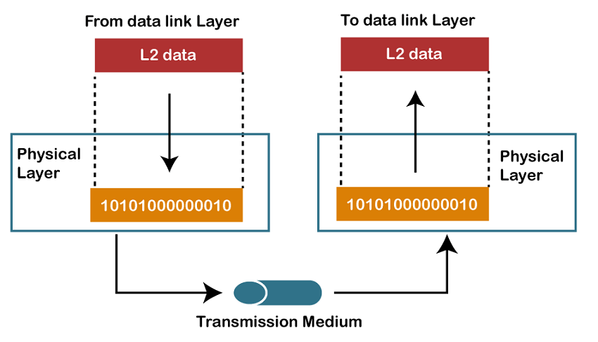
physical layer is responsible for the transmission and reception of unstructured raw data between a device and a physical
transmission medium. It converts the digital bits into electrical, radio, or optical signals. Layer specifications define characteristics such as voltage levels, the timing of voltage changes, physical data rates, maximum transmission distances, modulation scheme, channel access method and physical connectors. This includes the layout of
pins,
voltages, line
impedance, cable specifications, signal timing and frequency for wireless devices. Bit rate control is done at the physical layer and may define transmission mode as
simplex,
half duplex, and
full duplex. The components of a physical layer can be described in terms of a
network topology.
Bluetooth,
Ethernet, and
USB all have specifications for a physical layer.
Layer 2: Data Link Layer
The
data link layer provides
node-to-node data transfer—a link between two directly connected nodes. It detects and possibly corrects errors that may occur in the physical layer. It defines the protocol to establish and terminate a connection between two physically connected devices. It also defines the protocol for
flow control between them.
IEEE 802 divides the data link layer into two sublayers:
[6]
- Medium access control (MAC) layer – responsible for controlling how devices in a network gain access to a medium and permission to transmit data.
- Logical link control (LLC) layer – responsible for identifying and encapsulating network layer protocols, and controls error checking and frame synchronization.
Layer 3: Network Layer
The
network layer provides the functional and procedural means of transferring variable length
data sequences (called
packets) from one node to another connected in "different networks". A network is a medium to which many nodes can be connected, on which every node has an
address and which permits nodes connected to it to transfer messages to other nodes connected to it by merely providing the content of a message and the address of the destination node and letting the network find the way to deliver the message to the destination node, possibly
routing it through intermediate nodes. If the message is too large to be transmitted from one node to another on the data link layer between those nodes, the network may implement message delivery by splitting the message into several fragments at one node, sending the fragments independently, and reassembling the fragments at another node. It may, but does not need to, report delivery errors.
Message delivery at the network layer is not necessarily guaranteed to be reliable; a network layer protocol may provide reliable message delivery, but it need not do so.
A number of layer-management protocols, a function defined in the
management annex, ISO 7498/4, belong to the network layer. These include routing protocols, multicast group management, network-layer information and error, and network-layer address assignment. It is the function of the payload that makes these belong to the network layer, not the protocol that carries them.
[7]
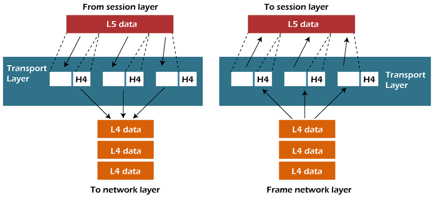
Layer 4: Transport Layer
The
transport layer provides the functional and procedural means of transferring variable-length data sequences from a source to a destination host, while maintaining the quality of service functions.
The transport layer controls the reliability of a given link through flow control,
segmentation/desegmentation, and error control. Some protocols are state- and connection-oriented. This means that the transport layer can keep track of the segments and re-transmit those that fail delivery. The transport layer also provides the acknowledgement of the successful data transmission and sends the next data if no errors occurred. The transport layer creates segments out of the message received from the application layer. Segmentation is the process of dividing a long message into smaller messages.
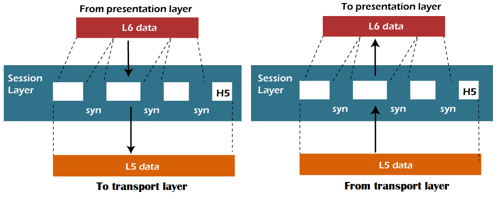
Layer 5: Session Layer
The
session layer controls the dialogues (connections) between computers. It establishes, manages and terminates the connections between the local and remote application. It provides for
full-duplex,
half-duplex, or
simplex operation, and establishes procedures for checkpointing, suspending, restarting, and terminating a session. In the OSI model, this layer is responsible for gracefully closing a session, which is handled in the
Transmission Control Protocol at the transport layer in the Internet Protocol Suite. This layer is also responsible for session checkpointing and recovery, which is not usually used in the Internet Protocol Suite. The session layer is commonly implemented explicitly in application environments that use
remote procedure calls.
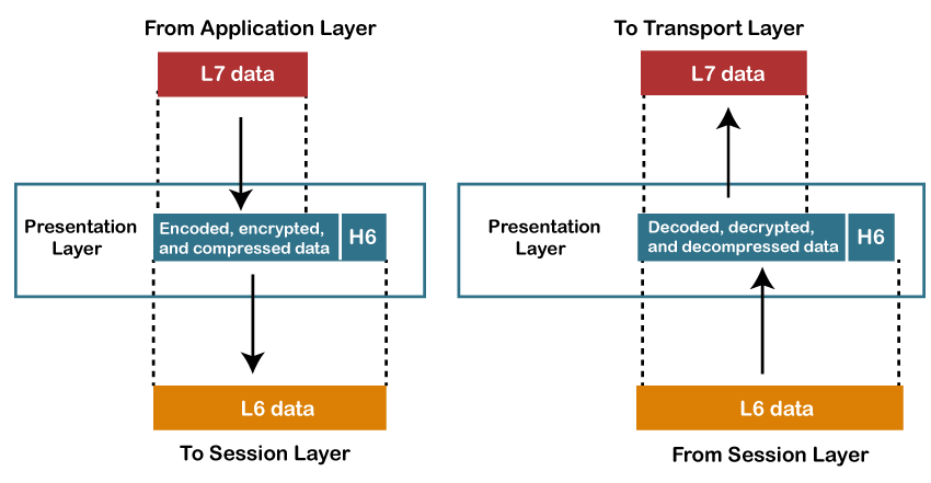
Layer 6: Presentation Layer
The
presentation layer establishes context between application-layer entities, in which the application-layer entities may use different syntax and semantics if the presentation service provides a mapping between them. If a mapping is available, presentation protocol data units are encapsulated into session protocol data units and passed down the
protocol stack.
This layer provides independence from data representation by translating between application and network formats. The presentation layer transforms data into the form that the application accepts. This layer formats data to be sent across a network. It is sometimes called the syntax layer.
[9] The presentation layer can include compression functions.
[10] The Presentation Layer negotiates the Transfer Syntax.
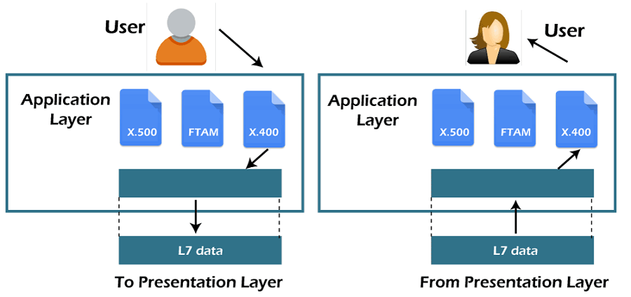
Layer 7: Application Layer
The
application layer is the OSI layer closest to the end user, which means both the OSI application layer and the user interact directly with the software application. This layer interacts with software applications that implement a communicating component. Such application programs fall outside the scope of the OSI model. Application-layer functions typically include identifying communication partners, determining resource availability, and synchronizing communication. When identifying communication partners, the application layer determines the identity and availability of communication partners for an application with data to transmit. The most important distinction in the application layer is the distinction between the application-entity and the application. For example, a reservation website might have two application-entities: one using HTTP to communicate with its users, and one for a remote database protocol to record reservations. Neither of these protocols have anything to do with reservations. That logic is in the application itself. The application layer per se has no means to determine the availability of resources in the network.
Protocol Layering:-
Protocol layering is a common technique to simplify networking designs by dividing them into functional layers, and assigning protocols to perform each layer's task.
For example, it is common to separate the functions of data delivery and connection management into separate layers, and therefore separate protocols. Thus, one protocol is designed to perform data delivery, and another protocol, layered above the first, performs connection management. The data delivery protocol is fairly simple and knows nothing of connection management. The connection management protocol is also fairly simple, since it doesn't need to concern itself with data delivery.
Protocol layering produces simple protocols, each with a few well-defined tasks. These protocols can then be assembled into a useful whole. Individual protocols can also be removed or replaced as needed for particular applications.
OSI Model
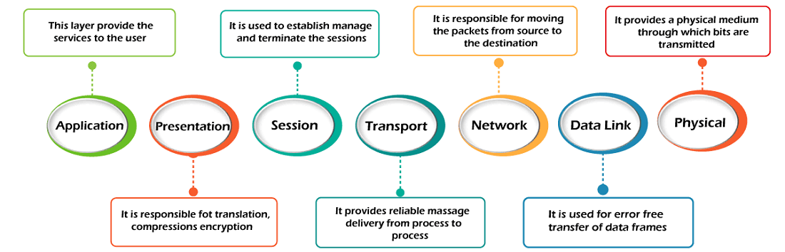
- OSI stands for Open System Interconnection is a reference model that describes how information from a software application in one computer moves through a physical medium to the software application in another computer.
- OSI consists of seven layers, and each layer performs a particular network function.
- OSI model was developed by the International Organization for Standardization (ISO) in 1984, and it is now considered as an architectural model for the inter-computer communications.
- OSI model divides the whole task into seven smaller and manageable tasks. Each layer is assigned a particular task.
- Each layer is self-contained, so that task assigned to each layer can be performed independently.
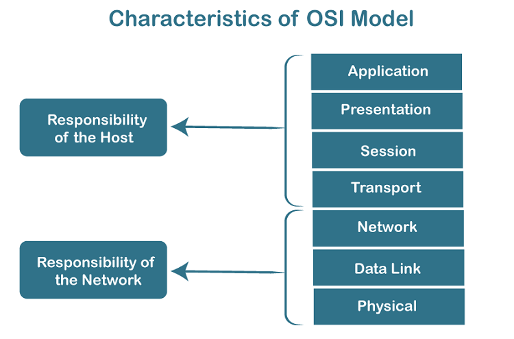
Characteristics of OSI Model:
- The OSI model is divided into two layers: upper layers and lower layers.
- The upper layer of the OSI model mainly deals with the application related issues, and they are implemented only in the software. The application layer is closest to the end user. Both the end user and the application layer interact with the software applications. An upper layer refers to the layer just above another layer.
- The lower layer of the OSI model deals with the data transport issues. The data link layer and the physical layer are implemented in hardware and software. The physical layer is the lowest layer of the OSI model and is closest to the physical medium. The physical layer is mainly responsible for placing the information on the physical medium.
Functions of the OSI Layers:-
The seven layers of the OSI Basic Reference Model are (from bottom to top):
- The Physical Layer describes the physical properties of the various communications media, as well as the electrical properties and interpretation of the exchanged signals. Ex: this layer defines the size of Ethernet coaxial cable, the type of BNC connector used, and the termination method.
- The Data Link Layer describes the logical organization of data bits transmitted on a particular medium. Ex: this layer defines the framing, addressing and checksumming of Ethernet packets.
- The Network Layer describes how a series of exchanges over various data links can deliver data between any two nodes in a network. Ex: this layer defines the addressing and routing structure of the Internet.
- The Transport Layer describes the quality and nature of the data delivery. Ex: this layer defines if and how retransmissions will be used to ensure data delivery.
- The Session Layer describes the organization of data sequences larger than the packets handled by lower layers. Ex: this layer describes how request and reply packets are paired in a remote procedure call.
- The Presentation Layer describes the syntax of data being transferred. Ex: this layer describes how floating point numbers can be exchanged between hosts with different math formats.
- The Application Layer describes how real work actually gets done. Ex: this layer would implement file system operations.
Physical layer
- The main functionality of the physical layer is to transmit the individual bits from one node to another node.
- It is the lowest layer of the OSI model.
- It establishes, maintains and deactivates the physical connection.
- It specifies the mechanical, electrical and procedural network interface specifications.
Functions of a Physical layer:
- Line Configuration: It defines the way how two or more devices can be connected physically.
- Data Transmission: It defines the transmission mode whether it is simplex, half-duplex or full-duplex mode between the two devices on the network.
- Topology: It defines the way how network devices are arranged.
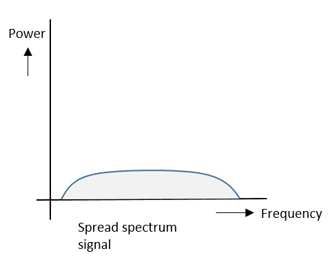
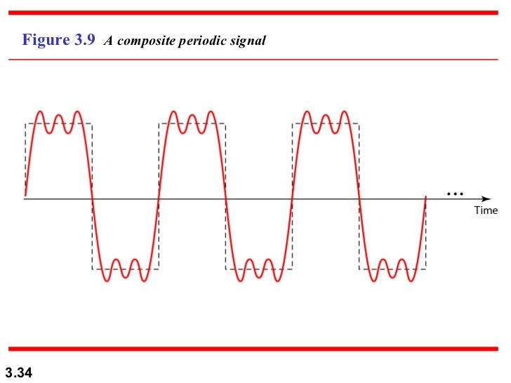
- Signals: It determines the type of the signal used for transmitting the information.
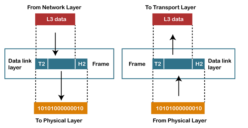
Data-Link Layer
- This layer is responsible for the error-free transfer of data frames.
- It defines the format of the data on the network.
- It provides a reliable and efficient communication between two or more devices.
- It is mainly responsible for the unique identification of each device that resides on a local network.
- It contains two sub-layers:
- Logical Link Control Layer
- It is responsible for transferring the packets to the Network layer of the receiver that is receiving.
- It identifies the address of the network layer protocol from the header.
- It also provides flow control.
- Media Access Control Layer
- A Media access control layer is a link between the Logical Link Control layer and the network's physical layer.
- It is used for transferring the packets over the network.
Functions of the Data-link layer
- Framing: The data link layer translates the physical's raw bit stream into packets known as Frames. The Data link layer adds the header and trailer to the frame. The header which is added to the frame contains the hardware destination and source address.

- Physical Addressing: The Data link layer adds a header to the frame that contains a destination address. The frame is transmitted to the destination address mentioned in the header.
- Flow Control: Flow control is the main functionality of the Data-link layer. It is the technique through which the constant data rate is maintained on both the sides so that no data get corrupted. It ensures that the transmitting station such as a server with higher processing speed does not exceed the receiving station, with lower processing speed.
- Error Control: Error control is achieved by adding a calculated value CRC (Cyclic Redundancy Check) that is placed to the Data link layer's trailer which is added to the message frame before it is sent to the physical layer. If any error seems to occurr, then the receiver sends the acknowledgment for the retransmission of the corrupted frames.
- Access Control: When two or more devices are connected to the same communication channel, then the data link layer protocols are used to determine which device has control over the link at a given time.
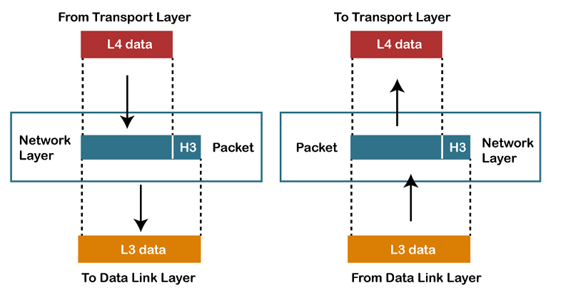
Network Layer
- It is a layer 3 that manages device addressing, tracks the location of devices on the network.
- It determines the best path to move data from source to the destination based on the network conditions, the priority of service, and other factors.
- The Data link layer is responsible for routing and forwarding the packets.
- Routers are the layer 3 devices, they are specified in this layer and used to provide the routing services within an internetwork.
- The protocols used to route the network traffic are known as Network layer protocols. Examples of protocols are IP and Ipv6.
Functions of Network Layer:
- Internetworking: An internetworking is the main responsibility of the network layer. It provides a logical connection between different devices.
- Addressing: A Network layer adds the source and destination address to the header of the frame. Addressing is used to identify the device on the internet.
- Routing: Routing is the major component of the network layer, and it determines the best optimal path out of the multiple paths from source to the destination.
- Packetizing: A Network Layer receives the packets from the upper layer and converts them into packets. This process is known as Packetizing. It is achieved by internet protocol (IP).
Transport Layer
- The Transport layer is a Layer 4 ensures that messages are transmitted in the order in which they are sent and there is no duplication of data.
- The main responsibility of the transport layer is to transfer the data completely.
- It receives the data from the upper layer and converts them into smaller units known as segments.
- This layer can be termed as an end-to-end layer as it provides a point-to-point connection between source and destination to deliver the data reliably.
The two protocols used in this layer are:
- Transmission Control Protocol
- It is a standard protocol that allows the systems to communicate over the internet.
- It establishes and maintains a connection between hosts.
- When data is sent over the TCP connection, then the TCP protocol divides the data into smaller units known as segments. Each segment travels over the internet using multiple routes, and they arrive in different orders at the destination. The transmission control protocol reorders the packets in the correct order at the receiving end.
- User Datagram Protocol
- User Datagram Protocol is a transport layer protocol.
- It is an unreliable transport protocol as in this case receiver does not send any acknowledgment when the packet is received, the sender does not wait for any acknowledgment. Therefore, this makes a protocol unreliable.
Functions of Transport Layer:
- Service-point addressing: Computers run several programs simultaneously due to this reason, the transmission of data from source to the destination not only from one computer to another computer but also from one process to another process. The transport layer adds the header that contains the address known as a service-point address or port address. The responsibility of the network layer is to transmit the data from one computer to another computer and the responsibility of the transport layer is to transmit the message to the correct process.
- Segmentation and reassembly: When the transport layer receives the message from the upper layer, it divides the message into multiple segments, and each segment is assigned with a sequence number that uniquely identifies each segment. When the message has arrived at the destination, then the transport layer reassembles the message based on their sequence numbers.
- Connection control: Transport layer provides two services Connection-oriented service and connectionless service. A connectionless service treats each segment as an individual packet, and they all travel in different routes to reach the destination. A connection-oriented service makes a connection with the transport layer at the destination machine before delivering the packets. In connection-oriented service, all the packets travel in the single route.
- Flow control: The transport layer also responsible for flow control but it is performed end-to-end rather than across a single link.
- Error control: The transport layer is also responsible for Error control. Error control is performed end-to-end rather than across the single link. The sender transport layer ensures that message reach at the destination without any error.
Session Layer
- It is a layer 3 in the OSI model.
- The Session layer is used to establish, maintain and synchronizes the interaction between communicating devices.
Functions of Session layer:
- Dialog control: Session layer acts as a dialog controller that creates a dialog between two processes or we can say that it allows the communication between two processes which can be either half-duplex or full-duplex.
- Synchronization: Session layer adds some checkpoints when transmitting the data in a sequence. If some error occurs in the middle of the transmission of data, then the transmission will take place again from the checkpoint. This process is known as Synchronization and recovery.
Presentation Layer
- A Presentation layer is mainly concerned with the syntax and semantics of the information exchanged between the two systems.
- It acts as a data translator for a network.
- This layer is a part of the operating system that converts the data from one presentation format to another format.
- The Presentation layer is also known as the syntax layer.
Functions of Presentation layer:
- Translation: The processes in two systems exchange the information in the form of character strings, numbers and so on. Different computers use different encoding methods, the presentation layer handles the interoperability between the different encoding methods. It converts the data from sender-dependent format into a common format and changes the common format into receiver-dependent format at the receiving end.
- Encryption: Encryption is needed to maintain privacy. Encryption is a process of converting the sender-transmitted information into another form and sends the resulting message over the network.
- Compression: Data compression is a process of compressing the data, i.e., it reduces the number of bits to be transmitted. Data compression is very important in multimedia such as text, audio, video.
Application Layer
- An application layer serves as a window for users and application processes to access network service.
- It handles issues such as network transparency, resource allocation, etc.
- An application layer is not an application, but it performs the application layer functions.
- This layer provides the network services to the end-users.
Functions of Application layer:
- File transfer, access, and management (FTAM): An application layer allows a user to access the files in a remote computer, to retrieve the files from a computer and to manage the files in a remote computer.
- Mail services: An application layer provides the facility for email forwarding and storage.
- Directory services: An application provides the distributed database sources and is used to provide that global information about various objects.
TCP/IP Protocol Suite
Protocol
A protocol is a set of rules that allows effective communication
The TCP/IP protocol suite (a.k.a. Internet Protocol Suite) is a collection of protocols that collectively provides the data transport services used on the Internet. They provide a robust and efficient mechanism for moving data between machines across computer networks.
The suite is split into five layers
TCP/IP Five Layer Model
- Application Layer - interfaces between application processes and transport layer services on host computer.
- Transport Layer - determines how to use the network layer to provide a virtual point-to-point connection between source and destination.
- Network/Internet Layer - layer by which data packets are routed from source to destination.
- Data Link Layer - provides data transfer control across the physical layer
- Physical Layer - the actual physical medium used for the transfer (e.g. cables, Infra red and microwave)
Important Notes:
HTTP (hypertext transfer protocol) -This is the workhorse of the Web.
SMTP,POP3,IMap4 – These are email protocols
TCP (Transmission control protocol) is a connection orientated protocol and is used to provides a reliable end to end connection.
UDP (used datagram protocol) is connection less protocol and doesn’t guarantee delivery. See UDP vs TCP- what is the Difference?
Applications will choose which transmission protocol to use based on their function. HTTP, POP3, IMAP4, SMTP and many more use TCP.
UDP is used more in utility applications like DNS, RIP (routing information protocol), DHCP.
IP (Internet Protocol) – This is the main networking protocol. There are two version of IP (
IPv4 and
IPV6).
ARP (address resolution Protocol) -Translates an IP address to a MAC or physical address.(IP4 networks)
Summary
The TCP/IP protocol suite is a collection of protocols that are used on the Internet.
It is named after two of the main protocols (TCP and IP) and uses a 4 layer networking model.
DoD Four-Layer Model:-
The Department of Defense Four-Layer Model was developed in the 1970s for the DARPA Internetwork Project that eventually grew into the Internet. The core Internet protocols adhere to this model, although the OSI Seven Layer Model is justly preferred for new designs.
The four layers in the DoD model, from bottom to top, are:
- The Network Access Layer is responsible for delivering data over the particular hardware media in use. Different protocols are selected from this layer, depending on the type of physical network.
- The Internet Layer is responsible for delivering data across a series of different physical networks that interconnect a source and destination machine. Routing protocols are most closely associated with this layer, as is the IP Protocol, the Internet's fundamental protocol.
- The Host-to-Host Layer handles connection rendezvous, flow control, retransmission of lost data, and other generic data flow management. The mutually exclusive TCP and UDP protocols are this layer's most important members.
- The Process Layer contains protocols that implement user-level functions, such as mail delivery, file transfer and remote login.